
LASS L-Angled Small System - Page 3
David Hunt - Gray, Tennessee, USA March 26, 2000
CONSTRUCTION (continued)
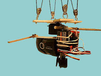
 Figure 1
(see page 7, for camera bracket improvements)
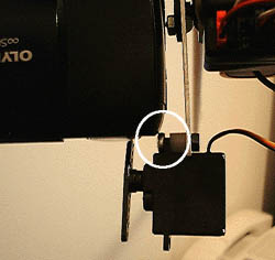 Figure 2
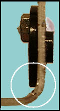
Figure 3
The Camera Bracket
3. Next we'll make the camera bracket which holds the camera and Shutter Servo. This will be mounted directly to the output of the Tilt Servo. Cut a 7 3/4" length of 1" by 1/16" aluminum stock. DO NOT drill any of the holes yet!
4. Bend the bracket 90º so that the distance from the inside of the angle to the end of the short leg is 2 3/4" (Figure 1).
CAUTION-if this leg gets shorter than
2 1/2" then the shutter servo mounting bolt could interfere with the camera. Figure 2 shows the mounting bolt and camera on a 2 1/2" bracket.
- CONSTRUCTION TIP
- To get the sharpest angle possible when bending the bracket, place the bracket in a vice. If you do not have access to a vice use a C-clamp and clamp another piece of aluminum stock across the place you want to make the bend. Grip the bracket with a pair of pliers near the proposed bend and use the pliers to bend the bracket over the top of the piece clamped across it. The wider the jaws of the pliers the better i.e. lineman's pliers.
6. Drill a 5/32" hole in the servo flange (but not through the bracket), insert the flange through the hole of the Camera Bracket (Figure 3). Now we must locate the position to drill the 5/32" hole through the Camera Bracket so we can bolt the flange to the bracket. Place the flange/bracket combination on the Tilt Servo shaft. (The Tilt Servo should still be bolted to the small angle along with the Pan Servo) Connect the Tilt Servo to the channel you will use on the Receiver and turn the Receiver on. Turn on the Transmitter and move the control to the "Full Tilt Up" position. Turn the Camera Bracket so the short leg points straight down which is the full tilt up position. Test the Camera Bracket position with the Transmitter control moved to the "Full Tilt Down" position.
The S3003 will not move a full 90º so you have to make a compromise. My thinking is that you are more likely to take pictures pointing straight down as opposed to straight ahead.Once you determine the proper range of movements, mark the bracket using the hole you drilled in the flange. Remove the bracket and drill the hole.
7. Use a nylon bolt and a nylon or metal nut, and mount the flange to the Camera Bracket. I use nylon because it is easy to cut off the excess length of the bolt so it will not interfere with mounting the camera.
(Figure 2 top center)
8. Locate the position of the camera mount hole by placing the camera on the bracket and drill a 1/4" hole.
(using Figure 1, the camera hangs upside down and faces to the right). The camera should have about 1/16" clearance with the nut holding the flange to the bracket (see Figure 2 top center)
I used a 1/4" Nylon pan head bolt to mount the camera. The threaded hole in the bottom of the Olympus Stylus Epic is only 3/16" deep. Add the 1/16" thickness of the aluminum bracket and that limits you to a bolt length of 1/4" max. Actually you will want the bolt slightly shorter to make sure you will be able to tighten the camera to the bracket. I've never seen a 1/4" bolt this short, so you will have to cut one to length. Nylon is preferable because there is less chance of cross-threading the plastic threads on the camera.
 Figure 4
9. Place the Shutter Servo on the end of the short leg of the Camera Bracket and use it as a guide to mark and drill a 5/32" hole.
Mount the Shutter Servo with a 4mm by 12mm bolt and nut, and a 1/4" long nylon spacer (Figure 2). The hole through the nylon space is slightly too small but the bolt can be screwed through the spacer using pliers and a screwdriver. Modify a servo arm to activate the shutter (Figure 4).
Figure 4
9. Place the Shutter Servo on the end of the short leg of the Camera Bracket and use it as a guide to mark and drill a 5/32" hole.
Mount the Shutter Servo with a 4mm by 12mm bolt and nut, and a 1/4" long nylon spacer (Figure 2). The hole through the nylon space is slightly too small but the bolt can be screwed through the spacer using pliers and a screwdriver. Modify a servo arm to activate the shutter (Figure 4).
See Addendum, page 7 for design improvements relating to shutter servo attachment
10. I mounted a 4 1/2 inch long piece of spruce to the top of the Camera Bracket to help protect the camera lens during landings (see picture at top of page).