
LASS L-Angled Small System - Page 4
David Hunt - Gray, Tennessee, USA March 26, 2000
CONSTRUCTION (continued)
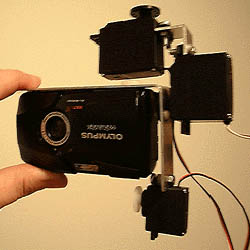 Figure 5
 Figure 6 (animated)
So far our LASS rig should look something like Figure 5.
Figure 6 (animated)
So far our LASS rig should look something like Figure 5.
Attaching the Remaining Components
11. First we will attach the Receiver to the front-facing side of Tilt Servo using rubber bands. This is easier to do if the Camera Bracket
has been removed.
Figure 6 shows an animation of how to attach the Receiver with a rubber band. The Pan & Tilt Servos are black and mounted to the small L-shaped piece. The Receiver is red to help distinguish it from the servos.
a.- Hold the Receiver next to the front-facing side of the Tilt Servo so that the connecting sockets are facing out and at the bottom.
b.- Slip the rubber band over the Pan Servo and bring it across the top of the Receiver. The inner portion of the rubber band should rest across the Tilt Servo flange used to mount the servo to the small angle.
c.- Pulling the rubber band tight, twist it at least once on the servo side.
d.- Bring the end around the bottom and slip the rubber band over the bottom end of the Receiver. The rubber band should rest just above the connecting sockets.
Figure 6a
 12. The Battery is attached the same way but on the other side of the Tilt Servo (Figure 6a). The Rubber band will wrap around both the Receiver and the Tilt Servo. The twist will be across the Receiver side.
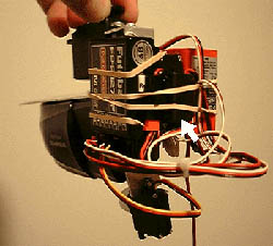 Figure 7
13. You can now attach the Camera Bracket and connect the servos and the On/Off Switch to the Receiver. Tuck the On/Off Switch under the rubber bands somewhere convenient
Figure 7
13. You can now attach the Camera Bracket and connect the servos and the On/Off Switch to the Receiver. Tuck the On/Off Switch under the rubber bands somewhere convenient
(arrow Figure 7).
14. Use a couple of wire ties to organize the wires.
CAUTION-leave the wires from the Shutter Servo loose to allow for the movement of the Camera Bracket.