
LASS L-Angled Small System - Page 6
David Hunt - Gray, Tennessee, USA March 26, 2000
ADDENDUM September 12, 2000
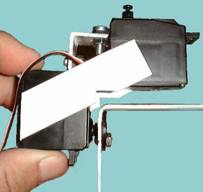 Figure 1
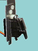 Figure 2
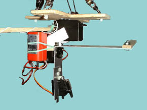 Figure 3
Back in May I posted a note on page 6 about a possible structural weakness. The flange on the Tilt Servo broke where it connects to the small aluminum "L". A couple of flights later the tilt servo flange broke, I noticed that half of the shutter servo flange was cracked. The shutter servo was repaired in the field by turning it over and placing a short length of clear plastic hose over the servo arm to make it long enough to reach the shutter button. I decided that the two flange failures were an indication of a weakness of this material for structural support. Two simple modifications make the LASS rig much stronger.
Figure 3
Back in May I posted a note on page 6 about a possible structural weakness. The flange on the Tilt Servo broke where it connects to the small aluminum "L". A couple of flights later the tilt servo flange broke, I noticed that half of the shutter servo flange was cracked. The shutter servo was repaired in the field by turning it over and placing a short length of clear plastic hose over the servo arm to make it long enough to reach the shutter button. I decided that the two flange failures were an indication of a weakness of this material for structural support. Two simple modifications make the LASS rig much stronger.
1. To relieve the stress on the pan and tilt servo flanges, two pieces of 0.080" thick styrene, 3/4" wide by 3" long were super glued to the servo cases as shown in figure 1. The super glue was applied only to the middle portion of the body of the servos. This will allow the servos to be disassembled if necessary. The notches were added after the braces were glued in place to allow clearance for the camera bracket rotation.
Styrene is found in most hobby shops in the USA. Thinner material could also be used, I just happened to have a sheet of 0.080" styrene on hand. Other stiff light material could be substituted for styrene.
2. To strengthen the attachment of the shutter servo I bolted an extra piece of aluminum to the camera bracket. This extra piece extends below the bottom of the shutter servo to protect it during landings (figure 2). If you have not built the LASS rig but are thinking about it, a better solution would be to cut the camera bracket longer so the shutter servo can be mounted using both flanges.